Creating a Virtual Interface Peer
Scenarios
Create a virtual interface peer based on service requirements.
If an IPv4 virtual interface peer already exists, only an IPv6 virtual interface peer can be created, and vice versa.
Procedure
Log in to the management console.
Click
 in the upper left corner and select a region and project.
In the service list, choose Network > Direct Connect.
In the navigation pane on the left, choose Direct Connect > Virtual Interfaces.
Locate the virtual interface and click its name.
Click Add below the virtual interface peer list.
Configure the parameters based on Table 1.
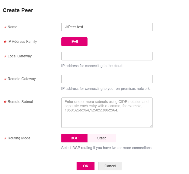
Figure 1 Adding a virtual interface peer
Table 1 Parameters required for adding a virtual interface peer¶ Parameter
Description
Name
Specifies the virtual interface peer name.
The name can contain 1 to 64 characters.
Only digits, letters, underscores (_), hyphens (-), and periods (.) are allowed.
IP Address Family
Specifies the IP version of the virtual interface peer. The value can be IPv4 or IPv6.
If an IPv4 virtual interface peer already exists, IPv6 is selected by default. Similarly, if an IPv6 virtual interface peer already exists, IPv4 is selected by default.
Note
The IP address type of the peer must be the same as that of the virtual gateway to be associated with the virtual interface to ensure normal network communication.
Local Gateway
Specifies the IP address for connecting to the cloud network.
If you select IPv4 for IP Address Family, the local gateway must be in the same IP address range as the remote gateway. Generally, a 30-bit mask is recommended.
Example IPv4 address: 192.168.0.1/30
Example IPv6 address: 1050:326b::/64
Remote Gateway
Specifies the IP address for connecting to your on-premises network.
If you select IPv4 for IP Address Family, the local gateway must be in the same IP address range as the remote gateway. Generally, a 30-bit mask is recommended.
Example IPv4 address: 192.168.0.2/30
Example IPv6 address: 1060:326b::/64
Remote Subnet
Specifies the subnets of your on-premises network.
Enter one or more unique subnets using CIDR notation and separate each entry with a comma. You can enter up to 50 subnets.
Example IPv4 subnets: 192.168.52.0/24,192.168.54.0/24
Example IPv6 subnets: 1050:326b::/64,1250:5:300c::/64
Caution
CAUTION:
Remote subnets cannot overlap with local subnets.
Using 100.64.0.0/10 as the remote subnet may cause services such as OBS, DNS, and API Gateway to become unavailable.
Routing Mode
Specifies the routing mode. Two options are available, Static and BGP.
If there are two or more connections, select BGP routing.
BGP ASN
Specifies the ASN of the BGP peer.
This parameter is mandatory when you select BGP for Routing Mode.
The value ranges from 1 to 4294967295. Do not use 64512, because it is used by the cloud.
BGP MD5 Authentication Key
Specifies the password used to authenticate the BGP peer using MD5. The value is case sensitive and cannot contain spaces.
This parameter is mandatory when you select BGP routing. You must ensure that the passwords on both gateways are the same.
The password can contain 8 to 255 characters.
The password must contain at least two types of the following characters: uppercase letters, lowercase letters, digits, and special characters ~`!,
.:;-_?"(){}[]/@#$%^&*+|\=
Description
Provides supplementary information about the virtual interface peer.
The description can contain a maximum of 128 characters.
Click OK.