Establishing Network Connectivity
Scenarios
Connect your on-premises data center to your VPC using Direct Connect if cloud servers in your VPC need to communicate with your on-premises servers.
Procedure
Request a connection.
Collect the information listed in Table 1.
Table 1 Information required for requesting a connection¶ Parameter
Description
Example Value
Domain Name
Your account name.
Hover the cursor over the username in the upper right corner and select My Credentials from the drop-down list.
On the My Credentials page, view the Domain Name.
abc123
Project ID
Project ID. Perform the following operations to obtain the project ID.
Hover the cursor over the username in the upper right corner and select My Credentials from the drop-down list.
In the lower part of the My Credentials page, locate the project.
View the project ID.
f9578ed9f9b1496da3ddf4ad29ccd891
Provider
The carrier that provides the connection.
others
Region
Region where the connection is created. Perform the following steps to view the region.
Log in to the management console.
Check the information in the upper left corner.
The part in the red box is the region.
Figure 1 Region
eu-ch2
Location
Location where the connection will be terminated.
location
Port Type
Port type. The value can be 1GE or 10GE.
1GE or 10GE
Bandwidth
Bandwidth of the connection, in Mbit/s.
If Port Type is set to 1GE, the bandwidth ranges from 2 Mbit/s to 1,000 Mbit/s.
If Port Type is set to 10GE, the bandwidth ranges from 2 Mbit/s to 10,000 Mbit/s.
100 Mbit/s
Name
Connection name. The name can contain a maximum of 64 characters. Only letters, digits, underscores (_), and hyphens (-) are allowed.
directconnect-001
Submit a request using any of the following methods:
Email: Send us an email with the title "Applying for Enabling the Direct Connect Service".
Hotline: Call us and provide the collected information to our customer service.
Contact our sales representative and provide the collected information to our sales representative.
Wait for the notification by email or from our customer service or sales representative.
Create a virtual gateway.
After the connection is created, log in to the management console.
Click
 in the upper left corner and select a region and project.
In the service list, choose Network > Direct Connect.
In the navigation pane on the left, choose Direct Connect > Virtual Gateways.
Click Create Virtual Gateway.
Configure the parameters.
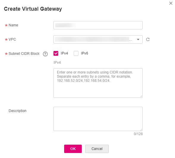
Figure 2 Create Virtual Gateway
Table 2 Parameter description¶ Parameter
Description
Name
Specifies the virtual gateway name.
The name can contain 1 to 64 characters.
Only digits, letters, underscores (_), hyphens (-), and periods (.) are allowed.
VPC
Specifies the VPC you want to access using the connection.
Subnet CIDR Block
Specifies the VPC subnets that can be accessed by the on-premises data center or network over the connection. Both IPv4 subnets and IPv6 subnets are supported.
You can enter one or more CIDR blocks and separate every entry with a comma (,).
Description
Provides supplementary information about the virtual gateway.
You can enter up to 128 characters.
Click OK.
Create a virtual interface.
In the navigation pane on the left, choose Direct Connect > Virtual Interfaces.
Click Create Virtual Interface.
Configure the parameters.
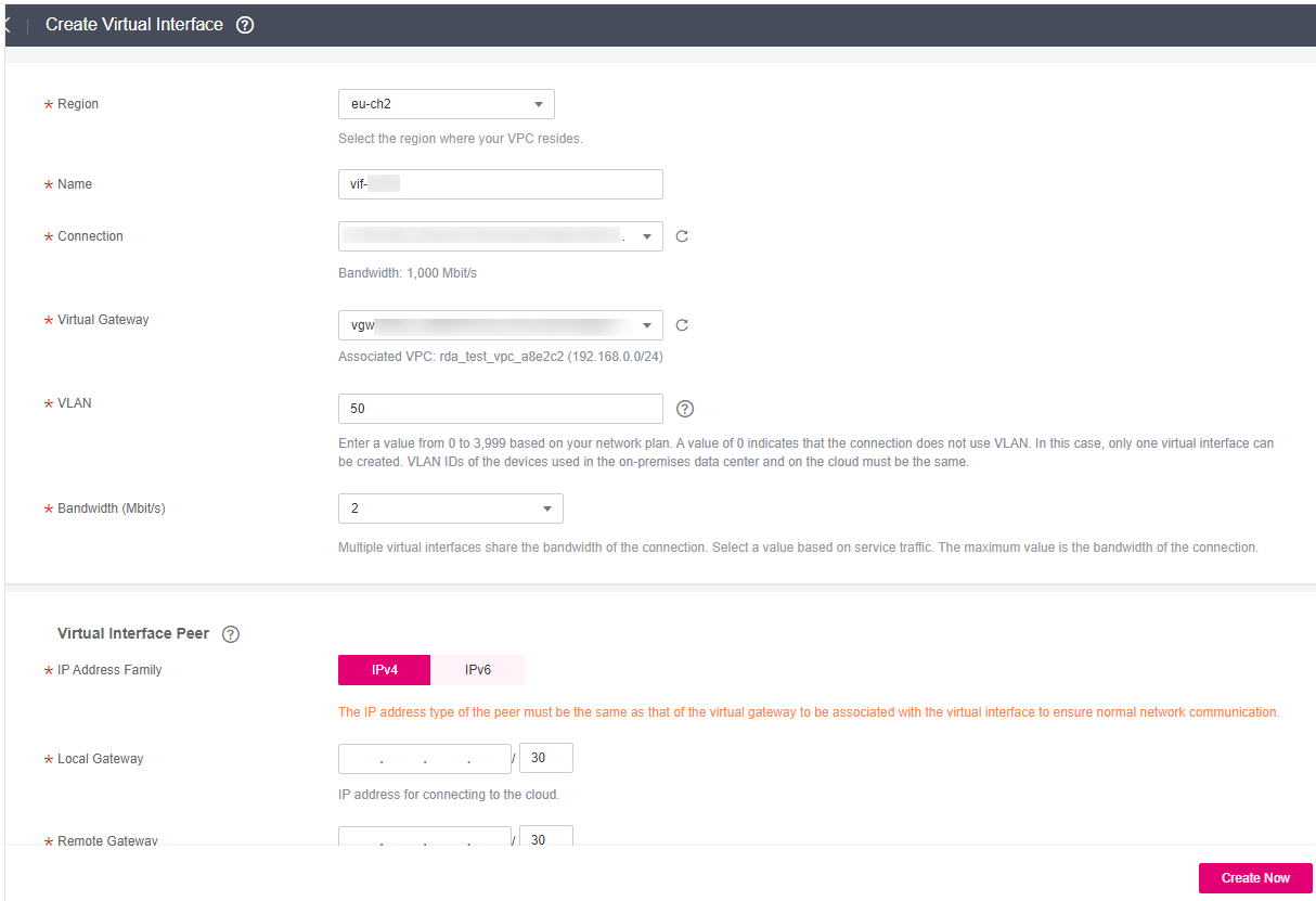
Figure 3 Creating a virtual interface
Table 3 Parameters for creating a virtual interface¶ Parameter
Description
Region
Specifies the region where the connection resides. You can also change the region in the upper left corner of the console.
Name
Specifies the virtual interface name.
The name can contain 1 to 64 characters.
Only digits, letters, underscores (_), hyphens (-), and periods (.) are allowed.
Connection
Specifies the connection you use to connect your on-premises network to the cloud.
Virtual Gateway
Specifies the virtual gateway to which the virtual interface will connect.
VLAN
Specifies the virtual interface VLAN ID.
The value ranges from 0 to 3999.
0 indicates the Layer 3 routing mode. Only one virtual interface can be created for each connection.
You need to configure the VLAN if you create a standard connection.
Bandwidth
Specifies the bandwidth that can be used by the virtual interface, in Mbit/s. The maximum bandwidth of a virtual interface cannot exceed that of the connection.
IP Address Family
Specifies the IP version of the virtual interface peer. The value can be IPv4 or IPv6.
Note
The IP address type of the peer must be the same as that of the virtual gateway to be associated with the virtual interface to ensure normal network communication.
Local Gateway
Specifies the IP address for connecting to the cloud network.
If you select IPv4 for IP Address Family, the local gateway must be in the same IP address range as the remote gateway. Generally, a 30-bit mask is recommended.
Example IPv4 address: 192.168.0.1/30
Example IPv6 address: 1050:326b::/64
Remote Gateway
Specifies the IP address for connecting to your on-premises network.
If you select IPv4 for IP Address Family, the local gateway must be in the same IP address range as the remote gateway. Generally, a 30-bit mask is recommended.
Example IPv4 address: 192.168.0.2/30
Example IPv6 address: 1060:326b::/64
Remote Subnet
Subnets of your on-premises network.
Enter one or more unique subnets using CIDR notation and separate each entry with a comma. You can enter up to 50 subnets.
Example IPv4 subnets: 192.168.52.0/24,192.168.54.0/24
Example IPv6 subnets: 1050:326b::/64,1250:5:300c::/64
Caution
CAUTION:
Remote subnets cannot overlap with local subnets.
Using 100.64.0.0/10 as the remote subnet may cause services such as OBS, DNS, and API Gateway to become unavailable.
Routing Mode
Specifies the routing mode. Two options are available, Static and BGP.
If there are two or more connections, select BGP routing.
BGP ASN
Specifies the ASN of the BGP peer.
This parameter is mandatory when you select BGP for Routing Mode.
The value ranges from 1 to 4294967295. Do not use 64512, because it is used by the cloud.
BGP MD5 Authentication Key
Specifies the password used to authenticate the BGP peer using MD5. The value is case sensitive and cannot contain spaces.
This parameter is mandatory when you select BGP routing. You must ensure that the passwords on both gateways are the same.
The password can contain 8 to 255 characters.
The password must contain at least two types of the following characters: uppercase letters, lowercase letters, digits, and special characters ~`!,
.:;-_?"(){}[]/@#$%^&*+|\=
Description
Provides supplementary information about the virtual interface.
Note
When you configure the local and remote gateways, note the following:
Local gateway is used by the cloud for connecting to your on-premises network. After you configure Local Gateway on the console, the configuration will be automatically delivered to the gateway used by the cloud.
Remote gateway is used by your on-premises network for connecting to the cloud. After you configure Remote Gateway on the console, you also need to configure the gateway deployed in your equipment room.
The local gateway must be in the same CIDR block as the remote gateway, and this CIDR block cannot conflict with the local subnet configured on the virtual gateway or the remote subnet configured on the virtual interface.
Click Create Now.